![]()
| Parabolic headlamps have been used as reflection systems since the very beginning (1910) | ||||||
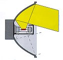
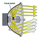
| The reflector surface has the shape of a paraboloid -
a parabola rotated round its own axis. Looking at the reflector from the front the upper
section of the reflector is used for the dipped beam. The light is source is positioned so that the light radiating upward is reflected downward on the road across the optical axis. The light is reflected virtually parallel except for the widening of the light beam depending on the size and position of the filament in the bulb. Optical patterns in the lens distribute the light to fulfil legal requirements. This is accomplished with two different types of optical patterns: vertical cylindrical elements for horizontal distribution of the light and prismatic elements at the height of the optical axis which serve to focus the light to provide better illumination of the most important points on the road. The lens in a parabolic headlamp for the dipped beam has an obvious optical pattern and provides typical light distribution. Today primary driving lamps and large H4 headlamps are laid out as parabolic systems. |
|
|||||