![]()
| New development technologies as well as calculation capacities and production methods have made production of FF headlamps possible during the last few years. | ||||||
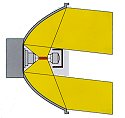
| FF headlamps have reflector surfaces with a free
spatial form. They can only be calculated and optimised with the aid of computers.
Different calculations strategies are used for laying out the the reflector surfaces. In
the present example the reflector is divided up into segments for illuminating different
segments of the roadway. This layout allows virtually the entire reflector surface to be
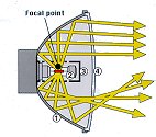
utilised for the dipped beam. The surfaces are positioned so that the light from all the reflector segments is reflected downward on the road. Focusing of the light rays and scattered light is accomplished directly by the reflector surface. This allows the use of clear cover lenses without optical pattern giving a brilliant impression. The cut off and illumination of the right hand edge of the road is achieved by the use of horizontal reflector segments. Whether the lens requires an optical pattern for distribution of the light depends largely on the reflector design. The light distribution at the road level can easily be adapted to special needs and requirements. Nearly all modern reflection type headlamp systems for dipped beam are equipped with FF reflectors.
|
|
|||||