The PLUM-4 polyvalent logic module adds fully automatic daytime running light (DRL) functionality to a vehicle's front turn signal lamps by operating them steadily when the engine is running, the parking brake is released, and the parking/tail lamps or headlamps are switched off. The turn signals still work normally; when the DRLs are on, signalling for a left turn (for example) will flash the left turn signal while the right one remains steady-lit, still providing the DRL function. Activating the hazard flashers (4-way flashers) overrides the DRL function; the turn signals on both sides of the vehicle will flash—all just like a factory installation.
This DRL implementation complies with US and Canadian DRL requirements, and has major advantages over headlamp-based DRLs. Because directional signals are legally required to shine light in a wide range of horizontal and vertical angles, the DRLs are likewise visible from a wide range of viewing angles for maximum conspicuity and safety benefit in avoiding angular collisions with pedestrians, bicyclists and other motorists. Turn signal bulbs cost much less, consume much less power and have a much longer lifespan than headlight bulbs. There is no undue glare with turn signal DRLs, as can be a problem with headlamp-based DRLs. And, it's much harder to forget to turn on your full lights at night, because the DRL color is amber rather than white so you don't see misleading reflections of your "headlamps" (actually your DRLs) in shiny surfaces after dark.
The PLUM-4 is all-new, and vastly improved over the previous-type
module.
Every single component is significantly upgraded, it's now fully
potted (weatherproof), it has four output channels instead of two and
higher current capacity, and it is easier to mount. The module is built
in the USA to my specifications.
Unlike the previous module, this new one is a 4-channel device able to
add daytime running light functionality to the front turn signals
and
add turn signal flashing to the front sidemarker
lights; previously you would have needed two modules, one
for each newly-added function. Of course, if you only want to do
one of these things, the new module will handle that just fine, too.
This compact, dependable module, when installed properly, will give years of trouble-free service. It comes with all the necessary connectors and can be installed under the hood, under the dash, or near the right or left front turn signal on a vehicle of just about any description. It is designed and intended to add an effective crash-preventive function to vehicles equipped with legitimate lamps and bulbs; it is not for use with "switchback LED bulbs" and other such unsafe playtoys.
Here are three short movies of added-on turn signal
DRLs in action:
Here is how the module gets connected into the car's wiring. This diagram shows all the hookups to add the DRL function to the front turn signals and add turn signal flashing to the front side marker lights; if you only wish to add the DRL function, you may disregard the side marker lights, their wiring, and the module's white and green wires. Click this diagram for a larger version in a new browser tab
: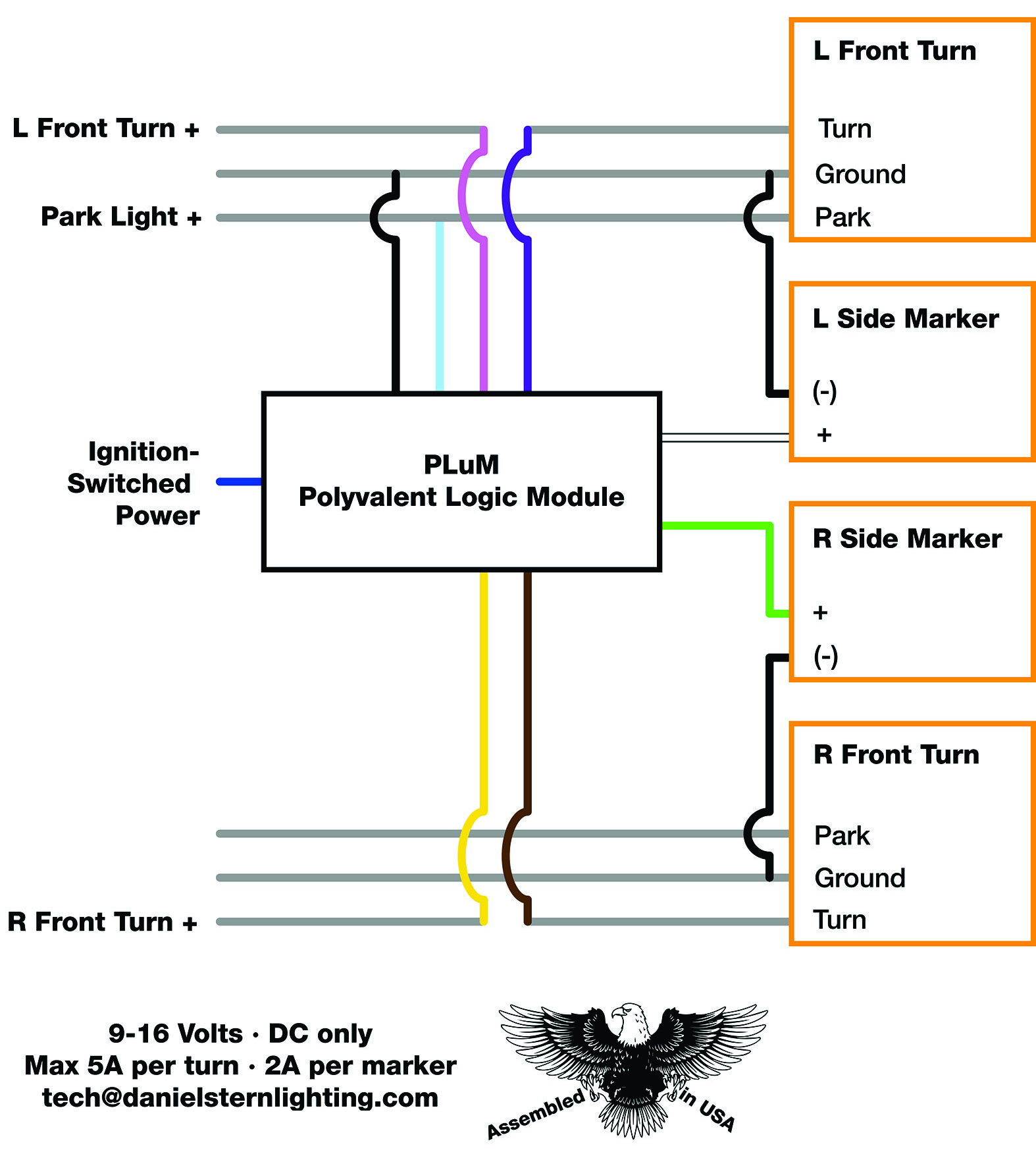
To add the DRL function, you will be making four
connections to existing wires on
one side of the car, and only two on the other side (plus one more
connection to an ignition-switched source of power).
The
module's yellow
and brown wires will connect to the cut ends of the front turn
signal
feed wire on one side of the vehicle, and the module's pink and
violet
wires will connect to the cut ends of the front turn signal feed wire on
the other side of the vehicle.
Most installers choose to mount
the
module on one side of the car, tucked out of harm's way (e.g. inside the
front bumper cover, behind the lamp housing, or in one front corner of
the engine bay), then extend the correct two module wires over to the
other side of the vehicle. Some installers choose instead to access the
applicable wires inside the passenger compartment, under the dash at the
base of the steering column.
In addition to the connections at the turn signals, you will need to locate a wire that is live with +12v when (and only when) the ignition is switched on. Many cars have a fusebox in the engine compartment, and you can often find an appropriate circuit there. If necessary, you can run a wire into the interior of the car. Select a circuit that's fused for at least 15 amps. This is what the module's dark blue wire is for, and it comes with fusebox tap-in adapters for easy, safe hookup.
Installation
Installation should take 20 to 60 minutes. You will need a wire cutter/strippers and a pair of pliers to make the connections. You will be using wire taps. The supplied ones are an excellent type called Posi-Taps. Don't substitute the fold-over-and-crunch "Scotchlok" type taps—really, please don't; you'll regret it later. If you need more Posi-Taps, you can get them directly from the maker.
These instructions assume that you will be installing the module near
the left front turn signal. If there is more room on the right side of
the vehicle or you prefer a mounting location on the right, simply read
"left" for "right" and vice-versa in these instructions.
Mount
the module out of harm's way. It is highly weatherproof and splashproof,
but please don't make it go swimming underwater for prolonged periods,
and don't mount it where the tires will constantly fling pebbles, ice,
and slush at it. You may lengthen any of the wires in order to place the module in an optimal location. Use
№ 16 primary wire. It is best to extend wires
using wire
of
the
same colour. If you can't, make sure to mark your
wires clearly so you will be able to make the proper connections.
- Locate the wires for
the left front turn signal. If you have a wiring diagram for the car,
this will help you identify these wires. If not, then you may need to
use a voltmeter or test light to identify the correct wires. Many
vehicles have combination park/turn signals with two-filament bulbs. The
dim filament is used for the parking lamp function, and the bright
filament is used for the turn signal function. These have three wires:
one feeding the dim filament (parking light), one feeding the bright
filament (turn signal), and one
ground.
- Connect the module's black wire
from the module to a good ground. This can be the vehicle's front
turn signal ground wire, or any convenient good
ground.
- Connect the module's light blue wire to
the vehicle's left parking lamp feed wire. This is a
tap-in connection; the parking lamp feed wire remains
uncut&mash;the module wire forms a tee junction with the
vehicle's wire.
- Cut the vehicle's left front turn signal feed wire, and strip
13&nbdp;mm (½") of insulation from each end. If your car has side
turn signal
repeaters on the fenders or sideview mirrors, and/or front sidemarker
lights that flash with the turn signals, you want to exclude these from
DRL operation—you want only the front turn signals to burn full
time as DRLs—so make sure to cut the turn signal feed wire as
close to the front turn signal as necessary to be "ahead" of where the
sidemarkers and/or repeaters tie into the turn signal feed wire.
- Connect the module's pink wire to the cut end of the
vehicle's left
front
turn signal feed wire that leads to the vehicle's wiring
harness.
Connect the module's violet wire to the
cut end of the vehicle's left front turn signal feed wire that
leads to the left front turn signal lamp.
- Locate the wire that feeds the vehicle's right front turn signal.
- Cut the vehicle's right front turn signal feed wire, and strip
13 mm (½") of insulation from each end.
- Connect the module's yellow wire to the
cut end of the
vehicle's right front turn signal feed wire that leads to the car
wiring harness. Connect the
brown wire to
the cut end of the vehicle's right front turn signal feed wire
that leads to the right front turn signal
lamp.
The module's dark blue wire
gets connected to a switched power circuit&mdashone that is
live
with +12v only when the ignition is switched on. Use a circuit that is
fused for at least 15 amps. Select the appropriate fusebox connector to
make this connection or, if you have a type of fuse not catered for in
the connector selection or wish to tap in elsewhere, use a suitable
connector or wire-joining technique.
Tying Into the Parking Brake
This is optional. For factory-type operation of the DRLs, add a Normally Closed (or Changeover) relay in the module's ground (black) wire. Such a relay can be furnished at the time of ordering the module. Hook it up this way:
- Relay terminal 85: tapped (tee-connection) into vehicle's parking brake warning light wire
- Relay terminal 86: To ignition-switched +12v (same as module's dark blue power wire
This way, the DRLs are lit when the vehicle's ignition
key is on, the parking lamps or headlamps are off, and the parking brake
is released—just like a factory installation. This allows
for the engine to be running without the DRLs operating when the car is
not moving.
Here's why it works:
This type of relay has continuity between 30 and 87a when there is
not voltage across 86 and 85. When there is voltage across
86 and 85, there is not continuity between 30 and 87a. And the
parking brake warning light switch provides a path to ground when the
brake is applied—no path to ground when the brake is released.
So: Ignition switch ON, parking brake APPLIED means power across
relay 86/86, which means no continuity between 30 and 87a. Module
has no ground, so DRLs do not light.
Ignition switch ON, parking brake RELEASED means no power across 85/86,
which means continuity between 30 and 87a. Module has ground, so DRLs
light.
Start the car (and release the parking brake, if you've tied into it). Both front turn signals should be steady-lit. Activate the left turn signal and see that the left signal blinks. Cancel the left turn signal and the turn signal lights will both come on steadily as DRL again. Repeat the test with the right signal.
Turn on the parking lights. Both turn signal filaments should go off, and only the park filament should be on (together with the car's front and rear sidemarker lights, tail lights, and dashboard lights). Turn the lights off and the turn signal filaments should come on as DRLs. If something isn't working, double check your wiring for errors.
Use tie-wraps and/or appropriate electrical tape to neaten up the wires as needed and secure them out of harm's way. Fasten the module firmly in position.